Rocker Locker Shore Power Adapter Installation Tips
You can watch our detailed video developing this product here, but here's also some written tips and important notes! Any other questions, as always feel free to reach out.
Tools & Additional Materials Required
- 1/8" Drill Bit for Piloting the holes with the template
- ~3/16" Drill bit (0.177 - 0.201" works) to drill the holes to size
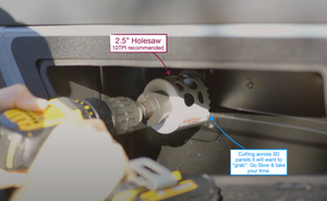
- 2.5" Hole Saw, I recommend a 10TPI. I like the ones from RockHard Tools
- Sharpie for Marking the center hole
- Center punch for marking the center hole
- 2.5mm & 3mm Hex Keys
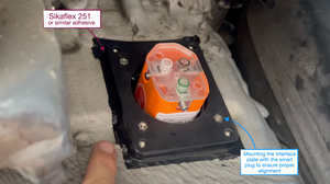
- Sikaflex 251 or similar sealing urethane adhesive
- Blue painters tape for masking
- A stepped drill bit to drill the re-entry for the cable. You can see how we ran it back in the van in the video here.
- You'll need 10/3 AWG marine grade wire for 30A shore power connections
Updated Drill Template
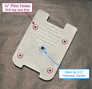
Rather than using and potentially damaging the front plate for drilling and templating we've included a 3D printed template with 1/8" drill bushings and a center hole for marking the holesaw center location.
Make sure the bracket is vertical and where you want it, and use the drill template to add the holes
Here are a few tips for using this Template:
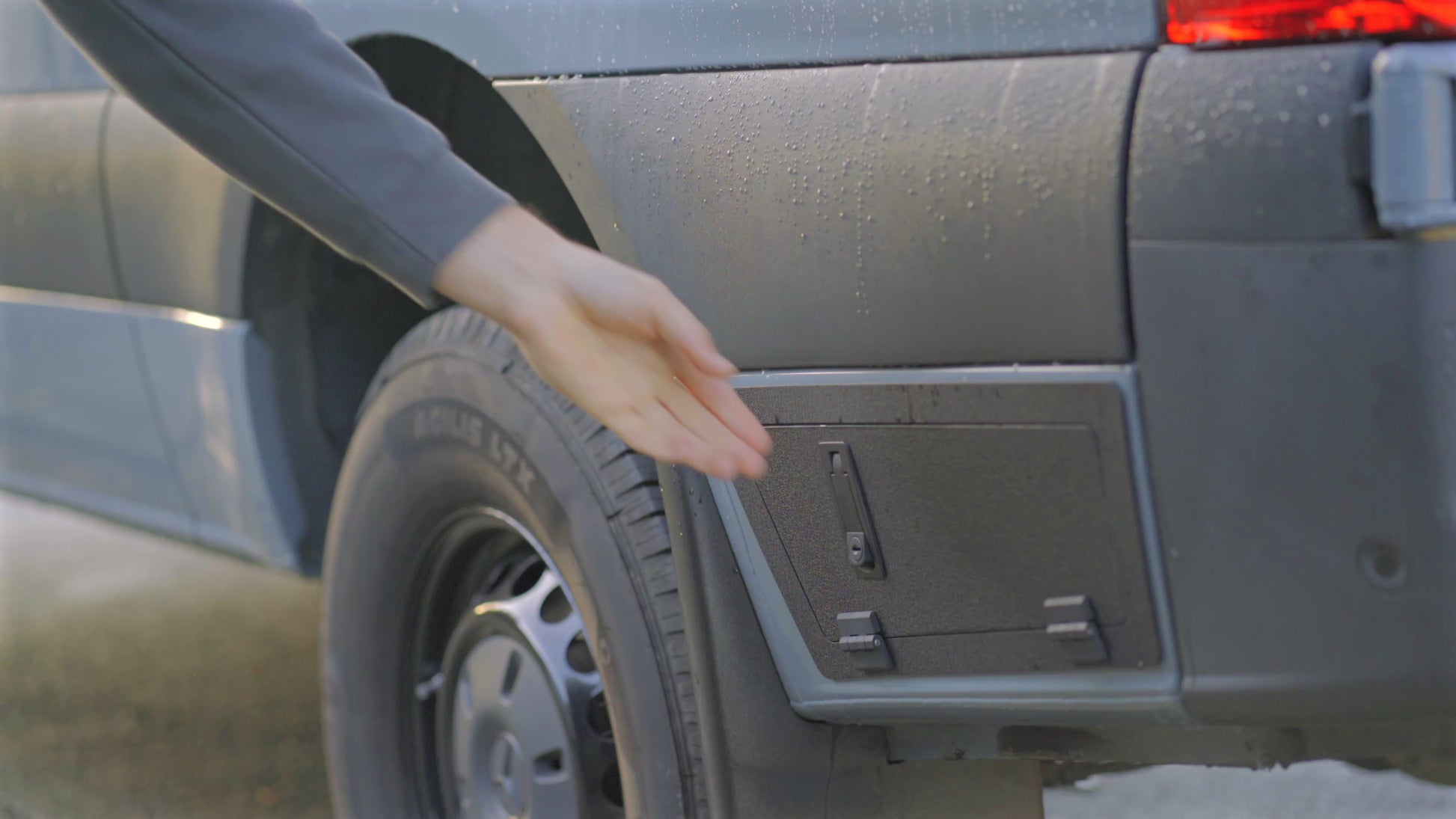
- It's recommended to test fit the part with the rubber grommet still installed in your van since this will help to index the bracket into the right spot.
- Drill the top two pilot holes first. You can then use these holes by pushing out the bushings to secure the template in place using two of the attachment screws.
- This will help hold the template in place while you drill the two bottom holes. Since these are on a slant on the body panel they are the two most difficult holes to drill.
!IMPORTANT: Once the location of the template is set drill the holes using sharp quality tools. There is not a lot of margin for error here, so if you don't feel comfortable or confident or have the right tools, professional installation is highly recommended. Moonraker Design Co. will not be held responsible for incorrect installation.
Always follow best practices for drilling and hole treatment:
- Centerpunch each hole location or use the drill guide template
- Center drill or pilot drill with a nice sharp small split tip cobalt drill or purpose made center drill.
- Drill to size using the recommended drill sizes.
- Debur the front & most importantly back side of the hole.
- Apply anti-corrosion treatment after test fitting. Our preferred is Rust Bullet, but any anti-corrosion paint will do.
Once the pilot holes are drilled open the holes up to a M4 clearance hole. The actual size is 0.177" which is a #16 drill bit, but any drill bit from about 0.177" - 0.201" works, so most people probably have a 3/16" drill bit which is 0.1875"
Drilling the Main Hole
The main 2.5" Hole also crosses some of the body panel 3D geometry. What can help here is using a 10TPI or fine tooth holesaw, but either way the cut will still want to "grab". Apply very little pressure and try to keep the holesaw spinning. If it does grab stop, reset get the holesaw spinning again and ease back into the cut.
Installing the Interface Plate
The interface plate needs to be bonded and sealed to the underside of the van to make sure the box is water tight. The easiest way to make sure it's in the right spot prior to sealing is mounting it with the SmartPlug inlet.
Once it's mounted add painters tape to mask the adhesive zone. It's a little tight in this area, so you may not be able to fit a caulking gun fully in this space. You can use adhesive dispensed onto a gloved finger instead.
Let the adhesive dry for about 30 mins & then remove the painters tape for a clean edge.
Adding Gasket Material to the Box
Included with your kit is a roll of Gasket material. This needs to be installed on both edges of the main box piece. You can see how we install this in the video here.
The material has a little bit of stretch to it in order to "thin" it out a little bit to match the edge thickness of the part. But don't stretch it too much. Also be mind full not to block all of the holes for the screws. If you do come back with a exacto knife or something to open them up a little bit.
Installing the SmartPlug
In the video I actually installed the SmartPlug first and then added the wires. This is doable, but it's also a little tight in that area to get the hexkey up there and tighten the screws. A better option is to probably "pre-attach" the wires to the SmartPlug and feed them through the inner lockbox adapter, van & interface plate opening.
Then you can screw the SmartPlug and adapter into the interface plate with the included M4x30mm Low Head Cap Screws using a 2.5mm Hex Key.
Once the Smart Plug is attached to the interface plate you can pass the wires through the 90deg liquid tight conduit grip that comes pre-installed into the center housing ring and close up the box with the back cover attaching to the interface plate with the M4x60mm mounting screws using a 3mm hex key.
If you have any questions about this install, please reach out at anytime.

